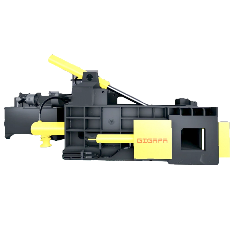
Working Principle of Hydraulic Horizontal Baling Press
A hydraulic horizontal baling press is an automated equipment that realizes material compression through hydraulic transmission system. Its core working principle can be divided into four key systems working together:
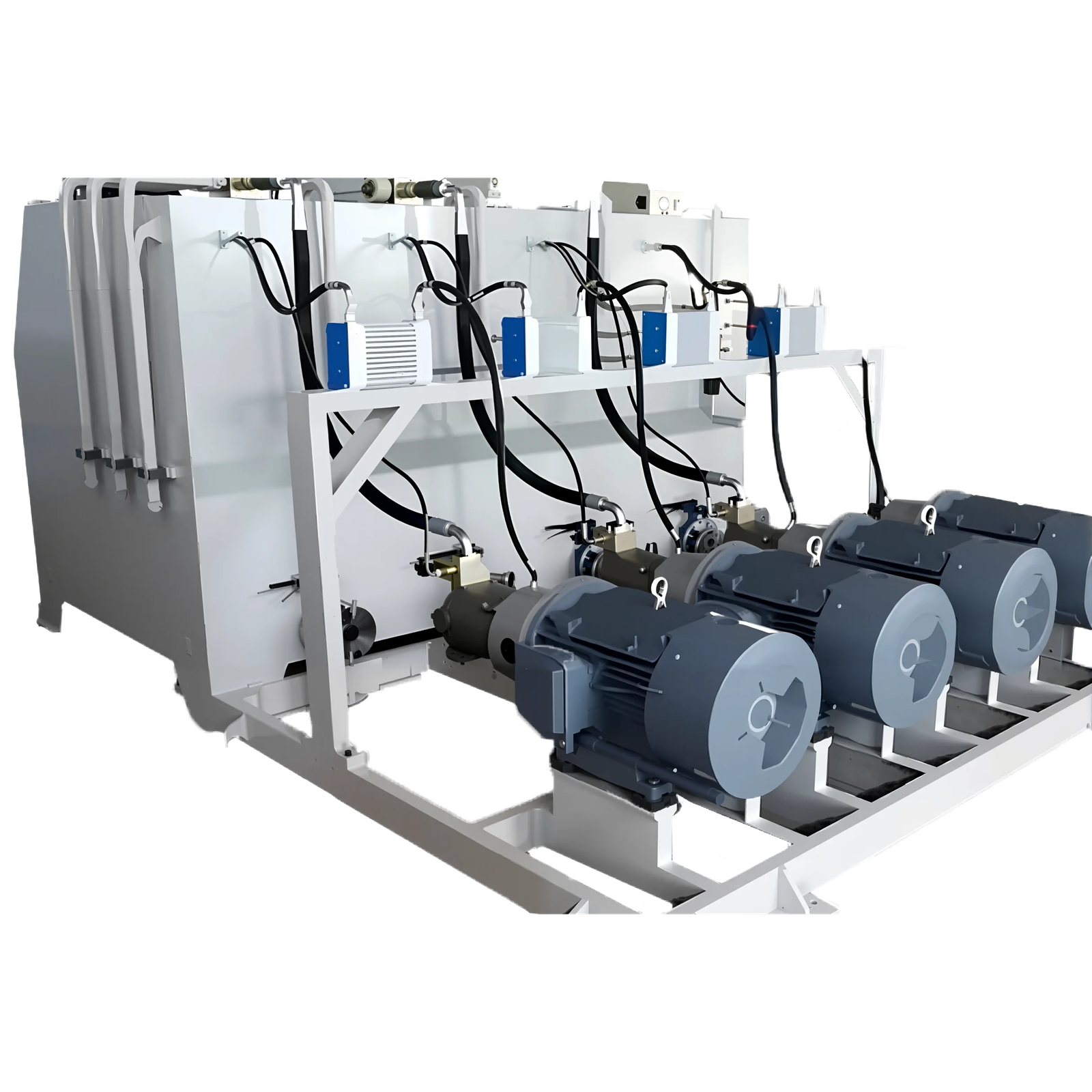
Hydraulic power system
- The motor drives the hydraulic pump to generate high-pressure oil flow
- The pressure regulating valve controls the output pressure (usually 15-30MPa)
- The hydraulic cylinder converts the oil pressure into mechanical thrust (typical thrust 50-300 tons)
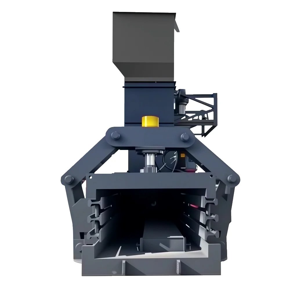
Material compression system
- Horizontally arranged compression chamber (size can be customized)
- The push plate is driven by the cylinder Downward linear reciprocating motion
- Progressive compression design (pre-compression + main compression two stages)
Automatic control system
- PLC programming controls the compression cycle (typical cycle 90-180 seconds)
- Photoelectric sensor monitors the material filling amount
- Pressure sensor realizes overload protection
Bundling output system
- Automatic threading/binding device (optional pneumatic or electric)
- Bag discharging mechanism (push bag/conveyor belt two methods)
- Door lock linkage safety device
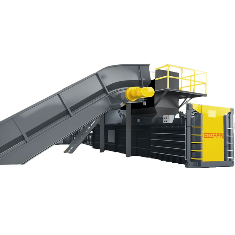
Workflow:
Feeding → pre-compression → main compression → pressure holding and shaping → automatic bundling → bag discharging and resetting. The whole process is automated through electro-hydraulic linkage, and the compression ratio can reach 5:1 to 8:1, significantly reducing the volume of materials.
Maintenance Guide for Hydraulic Horizontal Baling Press
I. Daily Maintenance
Hydraulic System Inspection
- Check hydraulic oil level daily (keep above midpoint)
- Monitor oil temperature (normal range: 30-60°C)
- Inspect hoses/fittings for leaks (replace seals immediately if found)
Lubrication
- Apply grease to compression chamber rails daily (recommended: lithium-based grease)
- Clean hydraulic cylinder rods weekly and apply anti-rust oil
- Lubricate bearings with high-temperature grease every 3 months
Key Component Checks
- Inspect electrical wiring for wear (visual check monthly)
- Test emergency stop button function (weekly)
- Clean sensor surfaces to prevent false triggering
II. Scheduled Maintenance (Recommended Intervals)
| Item | Interval | Procedure |
|---|---|---|
| Hydraulic oil change | 2000 hours | Use anti-wear hydraulic oil (ISO VG46) |
| Filter replacement | 500 hours | Clean oil tank simultaneously |
| System pressure calibration | 6 months | Adjust relief valve to nameplate specs |
| Fastener inspection | 3 months | Focus on anchor bolts/cylinder mounts |
III. Common Troubleshooting
Low Pressure
- Check relief valve failure
- Test hydraulic pump output (requires pressure gauge)
- Verify cylinder internal leakage (pressure drop <10%/10min)
Overheating (>70°C)
- Inspect cooler for clogging
- Verify oil viscosity (46±5cSt at 40°C)
- Check for continuous overload operation
Abnormal Operation
- Solenoid valve sticking (clean or replace spool)
- PLC signal failure (inspect sensor wiring)
- Mechanical obstruction (remove foreign objects)
IV. Professional Maintenance Advice
- Schedule comprehensive inspection by manufacturer every 2 years (including cylinder seal replacement)
- Maintain equipment operation log (record pressure/temperature/maintenance)
- Operators must hold proper hydraulic equipment certifications
Safety Warnings:
▶ Always power off and release hydraulic accumulator pressure before maintenance
▶ Never disconnect pressurized hydraulic lines
▶ Dispose of waste oil through professional recycling channels
-200x45.png)